SolidSteel parametric 4.0 improves some already existing functions and adds new, general functions.
This is primarily in response to feedback from various SolidSteel parametric users, and improvements and adjustments based on user feedback are also planned for the next updates.
 New Feature: Curved profiles
In addition to the familiar placement of profiles on straight lines as well as from point to point, in the new SolidSteel parametric version 4.0.0 profiles can now also be placed on circular arcs as well as on arced lines. Of course, these profiles can be offset, extended or shortened and rotated parallel to the line using the usual placement options of SolidSteel parametric.
In addition to surface and miter cutting, End Plates, Miter Plates and Ribs in curved profiles are of course also supported. Other connections adjacent to the bent profiles will also work perfectly, so long as the connection type is suitable.
In subsequent processes such as the equal part detection, the BOMs (unwound length) as well as the NC data (machining in straight parts), the curved profiles are considered accordingly.
 New Feature / Feature Update: Facade and roof module
With the SolidSteel parametric facade module, from an extensive library facade and roof elements can be placed, modified, deleted, edited and cut with just a few clicks.
 Creating, editing and deleting facade and roof elements
The Facade and Roof Elements function can be used to place facade elements and roof elements in the 3D model.
First, the size and series to be placed in the further process are selected from the extensive and expandable library. Then the orientation of the facade is defined and the area to be covered by the elements is selected. Afterwards, a preview appears directly if desired. In addition, of course, offsets can be set, sections and cutouts can be defined and optional longitudinal joints can be set.
Of course, overlaps of elements can already be defined during the construction, which can be transferred to subsequent elements.
As in all current SolidSteel parametric functions, the facade and roof elements can of course also be edited and deleted via convenient menus.


 New Feature: Roof extensions (facade module)
The roof extension can be used to extend an already existing roof surface to a second, adjoining roof surface.
Not only are all properties such as profile types and offsets adopted, but transitions between the two roof surfaces are also created automatically.
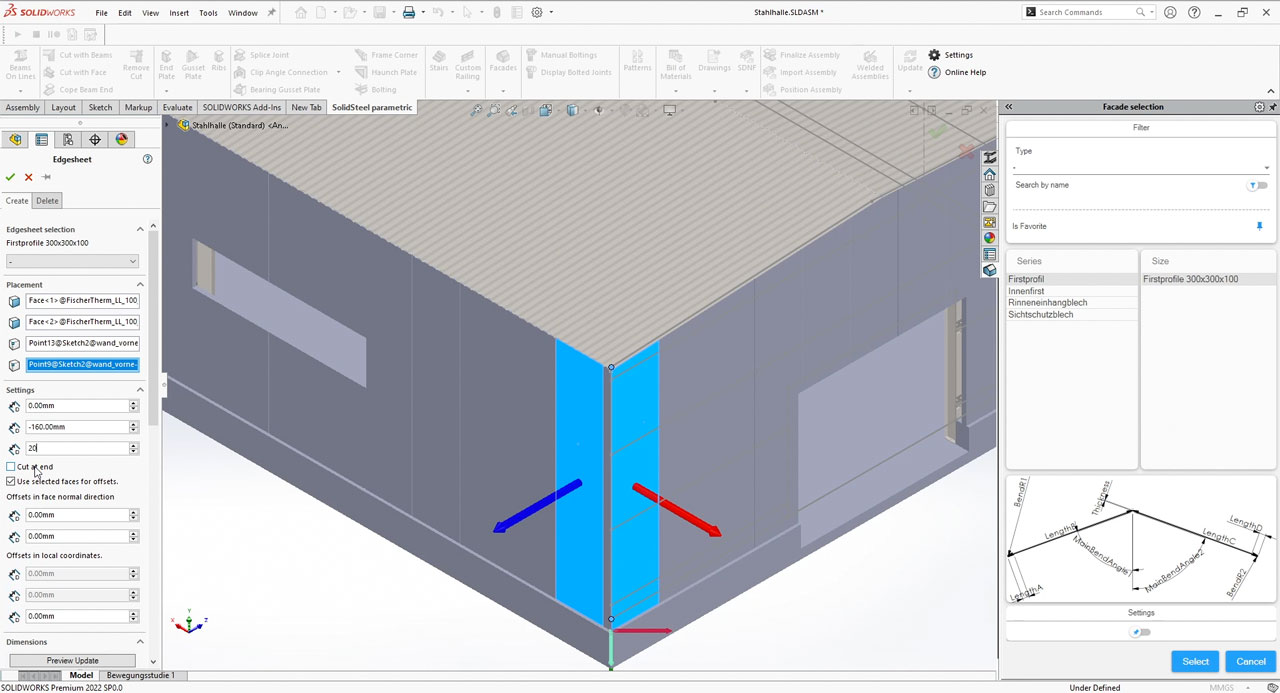
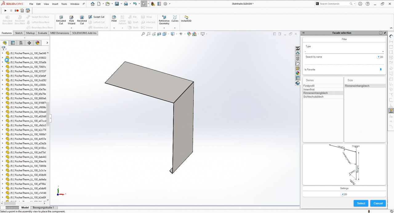
 New Feature: Edge sheets
Although the new feature "Edge sheets" is located in the Facade module, it is of course available to all users with SolidSteel parametric Design Package or Productivity Package. This function allows you to place profile-like bent sheets with an angle as a degree of freedom.
An example would be an eave sheet as a transition between roof and wall elements. This sheet always looks the same in principle, but must be adjusted accordingly due to the roof pitch. By selecting both surfaces, this takes over the edge sheet function and enables the placement of sheet metal templates in different installation situations.

With SolidSteel parametric 4.0 the usual SolidWorks context menus are also available for SolidSteel. Depending on the selected reference, relevant functions can be accessed directly in the 3D view of SOLIDWORKS. Afterwards the corresponding dialog opens, where the selection fields are already filled, as far as the context allows it.
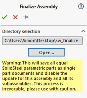
 New Feature: Equal part detection in the design
With the new function "Finalize assembly" SolidSteel parametric parts of all types with identical geometry are summarized. The consequence is that afterwards for all identical parts only one reference part (main part) exists in the assembly and all other identical parts are instances of this main part. The location of this reference part can be defined in the Path selection area.
 Feature Update: Extension of the gusset plate function
A new function in the gusset plate is the option of clipping the gusset plate at the pointed ends. The clipping is carried out perpendicular to the welded connection surface, and the distance of the clipping can be selected individually.
In addition to the clipping, the area for the holes has also been revised. In the new dialog, the difference between rows and columns is better recognizable thanks to a different division and labeling. In addition, the limit for drill holes (3 for columns, 2 for rows) has been removed. Any number of holes can now be placed in a gusset plate.
The new gusset plate PMP receives all inputs as long as the pin is set. This allows significantly faster work with gussets.
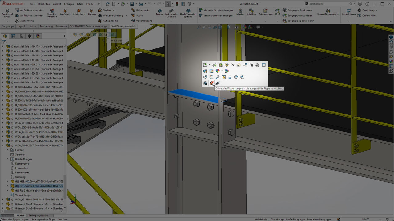
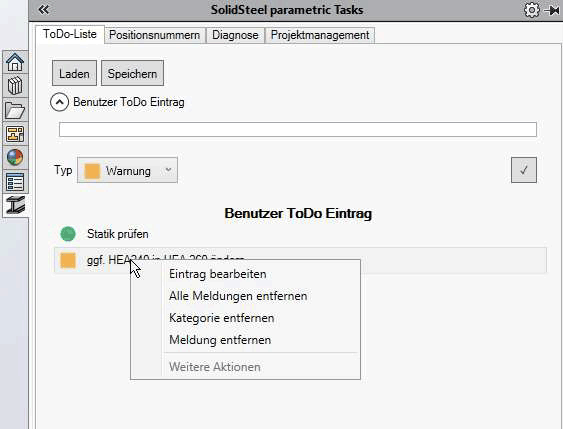
The functionality of the ToDo-Manager, which was mainly limited to deleting parts and messages so far, has been significantly extended in SolidSteel parametric 4.0. Whereas up to now only errors (e.g. update failed) or warnings (e.g. adjust the corresponding connections after changing a profile) were displayed in the ToDo-Manager, the new version adds the possibility of individual, user-defined messages.
The user defined ToDo's can be used, for example, to attach notes about necessary changes directly to the corresponding components.
In addition, the corresponding components can be selected, deleted and edited via the ToDo-Manager.
All icons of SolidSteel parametric have been revised and now fit much more pleasantly into the usual SOLIDWORKS look and now also support the dark mode.


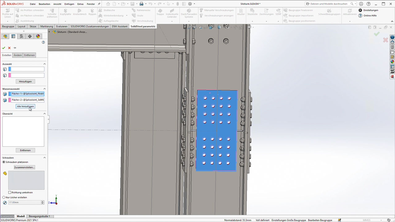
 Feature Update: Changing manual boltings
The dialog for manual boltings has been extended by a change function.
Until now, bolts could only be placed or deleted via the dialog. In contrast to creating, when changing a screw connection, it is not the holes or the corresponding surfaces that are selected, but the component containing a screw connection.

Modifications to flights of stairs don't break attached connections anymore, unless the type or series of the stringer beams is changed.
Proper warnings are now displayed when no preview binding components are found.
A problem with reading certain custom properties from beam tables was fixed.
Most connections and the creation of bills of materials should now work with beams whose construction lines are missing.
Crashes when selecting nothing in the preset combobox were fixed.
The incorrect position of certain half ribs was fixed.
Selectionbox focus issues in the custom railing dialog were fixed.
The profile manager service doesn't block the SOLIDWORKS journal file anymore
 Important Notes
New passwords are required for the installation.
You can obtain the new passwords:
from the Klietsch PasswordCenter (if you are a direct customer)
from the sales partner that you bought the product from.
Request "Update Passwords" for a version update.
Please add the update passwords to the license file. Together with the existing passwords the new version will be unlocked.
DSTV Assistant users will have to update it to v2.0 to ensure proper function with SolidSteel parametric v4.0.
You have additional questions about this topic? Our experts are pleased to help you. Just send us a Message or give us a call at +49 271 23167 0.
About us:
Company
Location
Job advertisements
Contact
Imprint
Support
remote maintenance
PTC Software solutions
PTC Creo parametric
PTC Creo Simulate
PTC Creo Elements/Direct Modeling
PTC Mathcad
Apps for SOLIDWORKS
SolidSteel parametric für SOLIDWORKS
AluFrame Assistant für SOLIDWORKS
DSTV Assistant für SOLIDWORKS
Apps for Siemens NX
SolidSteel parametric für Siemens NX
STAHL 2000 structural analysis software
STAHL 2000 structural analysis software
PTC Mathcad
Apps for Creo Elements/Direct Modeling
SolidSteel
SolidPipe
SolidWeld
SolidTube
DSTV Assistant
PART Assistant
PipeBending Assistant
BOM Assistant
Social Media


Data protection declaration - Terms and Conditions - Imprint
Copyright © 2000 - 2024 by Ingenieurgemeinschaft Klietsch GmbH - Siegen (Germany), all rights reserved.